This is the first in a series of posts where I will build a EVPN / VXLAN IP fabric starting with the basics. I intend these to be bite size, and subsequesnt labs will build gently on the knowledge gained. We will progress from a simple L2 IP fabric to a full blown multi tenancy Data Centre the spine and edge routing and bridging. I do not intend to cover much theory but merely to present configuration reference designs you can copy and try in your own lab. This can all be built in eve-ng.
The inspiration for this has come from my own difficulty in learning this new topic in a Juniper centric way, I learnt the theory but struggled to find full working configs there does not seem to much in the way of simple working examples I could find on the web.
You will need to be familiar with the Junos CLI and the basics of iBGP and eBGP. This lab was built using eve-ng and vqfx-10000, lets get started….
Step1. configure all the interface and loopback addresses.

#SPINE1 config
set system host-name SPINE1
delete interfaces
set interfaces xe-0/0/1 unit 0 family inet address 172.16.0.0/31
set interfaces xe-0/0/2 unit 0 family inet address 172.16.0.2/31
set interfaces xe-0/0/3 unit 0 family inet address 172.16.0.4/31
set interfaces lo0 unit 0 family inet address 10.0.255.1/32

#SPINE2 config
set system host-name SPINE2
delete interfaces
set interfaces xe-0/0/1 unit 0 family inet address 172.16.0.6/31
set interfaces xe-0/0/2 unit 0 family inet address 172.16.0.8/31
set interfaces xe-0/0/3 unit 0 family inet address 172.16.0.10/31
set interfaces lo0 unit 0 family inet address 10.0.255.2/32


#LEAF3 config
set system host-name LEAF3
delete interfaces
set interfaces xe-0/0/1 unit 0 family inet address 172.16.0.1/31
set interfaces xe-0/0/2 unit 0 family inet address 172.16.0.7/31
set interfaces lo0 unit 0 family inet address 10.0.255.3/32

#LEAF4 config
set system host-name LEAF4
delete interfaces
set interfaces xe-0/0/1 unit 0 family inet address 172.16.0.3/31
set interfaces xe-0/0/2 unit 0 family inet address 172.16.0.9/31
set interfaces lo0 unit 0 family inet address 10.0.255.4/32

#LEAF5 config
set system host-name LEAF5
delete interfaces
set interfaces xe-0/0/1 unit 0 family inet address 172.16.0.5/31
set interfaces xe-0/0/2 unit 0 family inet address 172.16.0.11/31
set interfaces lo0 unit 0 family inet address 10.0.255.5/32

# alldevices
<!-- wp:code -->
<pre class="wp-block-code"><code>#SPINE1 config
set system host-name SPINE1
delete interfaces
set interfaces xe-0/0/1 unit 0 family inet address 172.16.0.0/31
set interfaces xe-0/0/2 unit 0 family inet address 172.16.0.2/31
set interfaces xe-0/0/3 unit 0 family inet address 172.16.0.4/31
set interfaces lo0 unit 0 family inet address 10.0.255.1/32

#SPINE2 config
set system host-name SPINE2
delete interfaces
set interfaces xe-0/0/1 unit 0 family inet address 172.16.0.6/31
set interfaces xe-0/0/2 unit 0 family inet address 172.16.0.8/31
set interfaces xe-0/0/3 unit 0 family inet address 172.16.0.10/31
set interfaces lo0 unit 0 family inet address 10.0.255.2/32


#LEAF3 config
set system host-name LEAF3
delete interfaces
set interfaces xe-0/0/1 unit 0 family inet address 172.16.0.1/31
set interfaces xe-0/0/2 unit 0 family inet address 172.16.0.7/31
set interfaces lo0 unit 0 family inet address 10.0.255.3/32

#LEAF4 config
set system host-name LEAF4
delete interfaces
set interfaces xe-0/0/1 unit 0 family inet address 172.16.0.3/31
set interfaces xe-0/0/2 unit 0 family inet address 172.16.0.9/31
set interfaces lo0 unit 0 family inet address 10.0.255.4/32

#LEAF5 config
set system host-name LEAF5
delete interfaces
set interfaces xe-0/0/1 unit 0 family inet address 172.16.0.5/31
set interfaces xe-0/0/2 unit 0 family inet address 172.16.0.11/31
set interfaces lo0 unit 0 family inet address 10.0.255.5/32

# ALL DEVICES link to PFE
set interfaces em1 unit 0 family inet address 169.254.0.2/24
The first objective is to get all the loopbacks talking to each other, for this we will use eBGP. the primary reason for selecting eBGP is the support for ECMP ( load balancing over parrallel links), however for the initial lab it could be perfectly acceptable to use OSPF as the Underlay technology.
Step2. Configure eBGP as in the diagram, end goal, connectivity between all the loopbacks, load balanced.

Tasks are
- Configure the BGP peerings, ( use local-as and peer-as in the config )
- Export the loopbacks into BGP.
- Enable load balancing using BGP multipath and Load Balancing on the forwarding plane
- Verify Loopbacks can reach each other
- Verify multiple Paths are in the forwarding table.
##BGP PEERINGS
#SPINE1
set protocols bgp group underlay export LOOPBACK>UNDERLAY
set protocols bgp group underlay local-as 65101
set protocols bgp group underlay multipath multiple-as
set protocols bgp group underlay neighbor 172.16.0.1 peer-as 65103
set protocols bgp group underlay neighbor 172.16.0.3 peer-as 65104
set protocols bgp group underlay neighbor 172.16.0.5 peer-as 65105

#SPINE2
set protocols bgp group underlay export LOOPBACK>UNDERLAY
set protocols bgp group underlay local-as 65102
set protocols bgp group underlay multipath multiple-as
set protocols bgp group underlay neighbor 172.16.0.7 peer-as 65103
set protocols bgp group underlay neighbor 172.16.0.9 peer-as 65104
set protocols bgp group underlay neighbor 172.16.0.11 peer-as 65105

#LEAF3
set protocols bgp group underlay export LOOPBACK>UNDERLAY
set protocols bgp group underlay local-as 65103
set protocols bgp group underlay multipath multiple-as
set protocols bgp group underlay neighbor 172.16.0.0 peer-as 65101
set protocols bgp group underlay neighbor 172.16.0.6 peer-as 65102

#LEAF4
set protocols bgp group underlay export LOOPBACK>UNDERLAY
set protocols bgp group underlay local-as 65104
set protocols bgp group underlay multipath multiple-as
set protocols bgp group underlay neighbor 172.16.0.2 peer-as 65101
set protocols bgp group underlay neighbor 172.16.0.8 peer-as 65102

#LEAF5
set protocols bgp group underlay export LOOPBACK>UNDERLAY
set protocols bgp group underlay local-as 65105
set protocols bgp group underlay multipath multiple-as
set protocols bgp group underlay neighbor 172.16.0.4 peer-as 65101
set protocols bgp group underlay neighbor 172.16.0.10 peer-as 65102

#ALL DEVICES, EXPORT LOOPBACK INTO BGP
set policy-options policy-statement LOOPBACK>UNDERLAY term LOOPBACK from protocol direct
set policy-options policy-statement LOOPBACK>UNDERLAY term LOOPBACK from route-filter 10.0.255.0/24 orlonger
set policy-options policy-statement LOOPBACK>UNDERLAY term LOOPBACK then accept

#ALL DEVICES, LOAD BALANCE CONFIG
set routing-options forwarding-table export LOAD_BALANCE
set policy-options policy-statement LOAD_BALANCE term LOADBAL then load-balance per-packet
set policy-options policy-statement LOAD_BALANCE term LOADBAL then accept
Verification
root@LEAF3# run show bgp summary
Threading mode: BGP I/O
Groups: 1 Peers: 2 Down peers: 0
Table          Tot Paths  Act Paths Suppressed    History Damp State    Pending
inet.0
                       6          6          0          0          0          0
bgp.evpn.0
                       0          0          0          0          0          0
Peer                     AS      InPkt     OutPkt    OutQ   Flaps Last Up/Dwn State|#Active/Received/Accepted/Damped...
172.16.0.0            65101          5          4       0       0           7 3/3/3/0              0/0/0/0
172.16.0.6            65102          6          6       0       0           6 3/3/3/0              0/0/0/0

# peerings up to each spine

root@LEAF3> show route 10.0.255.0/24

inet.0: 11 destinations, 13 routes (11 active, 0 holddown, 0 hidden)
+ = Active Route, - = Last Active, * = Both

10.0.255.1/32      *[BGP/170] 00:01:42, localpref 100
                      AS path: 65101 I, validation-state: unverified
                    >  to 172.16.0.0 via xe-0/0/1.0
10.0.255.2/32      *[BGP/170] 00:01:42, localpref 100
                      AS path: 65102 I, validation-state: unverified
                    >  to 172.16.0.6 via xe-0/0/2.0
10.0.255.3/32      *[Direct/0] 00:37:06
                    >  via lo0.0
10.0.255.4/32      *[BGP/170] 00:01:38, localpref 100
                      AS path: 65101 65104 I, validation-state: unverified
                    >  to 172.16.0.0 via xe-0/0/1.0
                       to 172.16.0.6 via xe-0/0/2.0
                    [BGP/170] 00:01:38, localpref 100
                      AS path: 65102 65104 I, validation-state: unverified
                    >  to 172.16.0.6 via xe-0/0/2.0
10.0.255.5/32      *[BGP/170] 00:01:38, localpref 100
                      AS path: 65101 65105 I, validation-state: unverified
                    >  to 172.16.0.0 via xe-0/0/1.0
                       to 172.16.0.6 via xe-0/0/2.0
                    [BGP/170] 00:01:38, localpref 100
                      AS path: 65102 65105 I, validation-state: unverified
                    >  to 172.16.0.6 via xe-0/0/2.0

# multiple routes visable for loopbacks


root@LEAF3> ping 10.0.255.5 source 10.0.255.3
PING 10.0.255.5 (10.0.255.5): 56 data bytes
64 bytes from 10.0.255.5: icmp_seq=0 ttl=63 time=239.957 ms
64 bytes from 10.0.255.5: icmp_seq=1 ttl=63 time=140.861 ms

# ping test between loopbacks OK

root@LEAF3> show route forwarding-table destination 10.0.255.5
Routing table: default.inet
Internet:
Enabled protocols: Bridging,
Destination        Type RtRef Next hop           Type Index    NhRef Netif
10.0.255.5/32      user     0                    ulst   131070     3
                              172.16.0.0         ucst     1734     5 xe-0/0/1.0       #
                              172.16.0.6         ucst     1735     5 xe-0/0/2.0       # < - Multiple Paths show

# Load Balancing is verified
# All good lets move on :-)
Step3. iBGP overlay. end goal, iBGP peerings up between the the loopbacks running family evpn

- Create a new BGP group,
- Configure peering between the loopbacks
At this point in the lab all we really need is a iBGP peering between Leaf 3,4 & 5. However later we will include the spines for more advanced labs
Its important to note here that the spines currently will not participate in EVPN in anyway they will simply forward frames between the loopbacks on the leafs, I will cover some basic theory on this once we have this up and working.
LEAF3#
set protocols bgp group overlay local-address 10.0.255.3
set protocols bgp group overlay family evpn signaling
set protocols bgp group overlay peer-as 65200
set protocols bgp group overlay local-as 65200
set protocols bgp group overlay neighbor 10.0.255.5
set protocols bgp group overlay neighbor 10.0.255.4

LEAF4#
set protocols bgp group overlay local-address 10.0.255.4
set protocols bgp group overlay family evpn signaling
set protocols bgp group overlay peer-as 65200
set protocols bgp group overlay local-as 65200
set protocols bgp group overlay neighbor 10.0.255.3
set protocols bgp group overlay neighbor 10.0.255.5

LEAF5#
set protocols bgp group overlay local-address 10.0.255.5
set protocols bgp group overlay family evpn signaling
set protocols bgp group overlay peer-as 65200
set protocols bgp group overlay local-as 65200
set protocols bgp group overlay neighbor 10.0.255.3
set protocols bgp group overlay neighbor 10.0.255.4
OK notice the new address family this is the control plane we will be using for learning information like MAC address of devices on leafs, (more on this later ) , lets go verify this.
root@LEAF3# run show bgp summary
Threading mode: BGP I/O
Groups: 2 Peers: 4 Down peers: 0
Table          Tot Paths  Act Paths Suppressed    History Damp State    Pending
inet.0
                       6          6          0          0          0          0
bgp.evpn.0
                       0          0          0          0          0          0
Peer                     AS      InPkt     OutPkt    OutQ   Flaps Last Up/Dwn State|#Active/Received/Accepted/Damped...
10.0.255.4            65200          7          5       0       0        2:17 Establ
  bgp.evpn.0: 0/0/0/0
10.0.255.5            65200          7          6       0       0        2:17 Establ
  bgp.evpn.0: 0/0/0/0
OK Now lets move on to the VXAN CONFIG I will comment Leaf 5 , again I will break into the detail later but for lets just get a basic example working.
root@LEAF5

# show interfaces xe-0/0/0 | display set
set interfaces xe-0/0/0 unit 0 family ethernet-switching vlan members v10

# show vlans | display set
set vlans v10 vlan-id 10
set vlans v10 vxlan vni 2010

root@LEAF5# show switch-options | display set
set switch-options vtep-source-interface lo0.0
set switch-options route-distinguisher 10.0.255.5:1
set switch-options vrf-target target:65200:1

root@LEAF5# show routing-options | display set
set routing-options router-id 10.0.255.5

root@LEAF5# show protocols evpn | display set
set protocols evpn vni-options vni 2010 vrf-target target:65200:2010
set protocols evpn encapsulation vxlan
set protocols evpn extended-vni-list 2010

### the config is identical for the other nodes execept for
Node4 = 10.0.255.4
Node3 = 10.0.255.3
verification
root@HOST2# run ping 192.168.0.1
PING 192.168.0.1 (192.168.0.1): 56 data bytes
64 bytes from 192.168.0.1: icmp_seq=0 ttl=64 time=149.013 ms
64 bytes from 192.168.0.1: icmp_seq=1 ttl=64 time=141.040 ms


root@LEAF5# run show ethernet-switching table
   Vlan                MAC                 MAC      Logical                Active
   name                address             flags    interface              source
   v10                 50:00:00:0b:00:00   D        vtep.32769             10.0.255.3
   v10                 50:00:00:0c:00:00   D        xe-0/0/0.0
Notice above , this is something new, the MAC address is shown against a vtep interface.
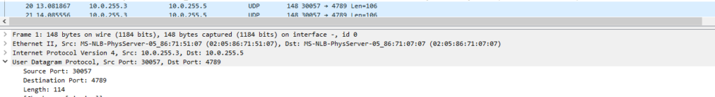
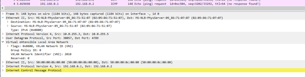
OK now we have a basic example working, lets break this down , how VXLAN is encapsulating this traffic and how EVPN is acting as a control plan. First all lets fire up Wireshark a look at the actual packets.
Lets start by following a packet , we are pinging from 192.168.0.1 to 192.168.0.2 these are in the same subnet, this is possible because thanks to VXLAN we have a virtual tunnel, the frames are being encapsulated in a VXLAN header and forwarded as a normal IP packet between the loopbacks ( VTEPS ) of Leaf3 and Leaf5 let see this in action in Wireshark
hint: when I start looking at this in wireshark, it was decoding VXLAN and showing the contents of the Tunnel I had to turn OFF VXLAN under enabled Analyse -> enabled protocols to show the real frames including the outer IP addresses.

Why do we not see return traffic in this capture ?
This is because the return traffic will be returning via xe-0/0/2, this is in effect random per flow. I will turn back on VXLAN as an enabled protocol on Wireshark.
Thinking Points:
What is the MAC address 02:05:86:71:51:07 ?
A: This is the Physical interface between Leaf3 and Spine 1 ( xe-0/0/1 )
Q:What is the IP address 10.0.255.3 and 10.0.255.5
A: These are the VTEPs these are the IPs the used within the fabric.
Q: What is the destination port 4789
A: This is the UDP port number of VXLAN
Q: What are the MAC addresses for the hosts 192.168.0.1 and 192.168.0.2
A: these can be seen in the capture ending in 0b:00:00 and 0c:00:00
The control plane
Lets looks the routes being advertised by BGP and break this down
root@LEAF3> show route advertising-protocol bgp 10.0.255.5 detail

default-switch.evpn.0: 6 destinations, 6 routes (6 active, 0 holddown, 0 hidden)
* 2:10.0.255.3:1::2010::50:00:00:0b:00:00/304 MAC/IP (1 entry, 1 announced)
 BGP group overlay type Internal
     Route Distinguisher: 10.0.255.3:1
     Route Label: 2010
     ESI: 00:00:00:00:00:00:00:00:00:00
     Nexthop: Self
     Localpref: 100
     AS path: [65200] I
     Communities: target:65200:1 encapsulation:vxlan(0x8)

* 2:10.0.255.3:1::2010::50:00:00:0b:00:00::192.168.0.1/304 MAC/IP (1 entry, 1 announced)
 BGP group overlay type Internal
     Route Distinguisher: 10.0.255.3:1
     Route Label: 2010
     ESI: 00:00:00:00:00:00:00:00:00:00
     Nexthop: Self
     Localpref: 100
     AS path: [65200] I
     Communities: target:65200:1 encapsulation:vxlan(0x8)

* 3:10.0.255.3:1::2010::10.0.255.3/248 IM (1 entry, 1 announced)
 BGP group overlay type Internal
     Route Distinguisher: 10.0.255.3:1
     Route Label: 2010
     PMSI: Flags 0x0: Label 2010: Type INGRESS-REPLICATION 10.0.255.3
     Nexthop: Self
     Localpref: 100
     AS path: [65200] I
     Communities: target:65200:1 encapsulation:vxlan(0x8)
     PMSI: Flags 0x0: Label 125: Type INGRESS-REPLICATION 10.0.255.3

{master:0}
The first thing to note is the number 2: or 3: is the evpn route type so here we have 2 type2 routes and a type3.
The type 2 route output is almost self expiatory, we can pick out the route distinguisher, VNI, MAC, and the community.
https://datatracker.ietf.org/doc/html/rfc7432#section-7.2
The type 3 simply signals how BUM traffic handled in this case ingress replication ( the alternative multicast is the OLD way ).
type 1 we will come to later.
Tables
There are a few moving parts here, The first table of interest is the bgp table the protocol next hop must be in the :vxlan.inet.0 table and if it is then the route is added to the bgp.evpn.0 table. , ( MPLS the inet.2 table but we are not using MPLS here ) , If you have a service provider back groud then this will sound familiar. This saves resources as there is no point keeping routes in the BGP table that we cannot get to.
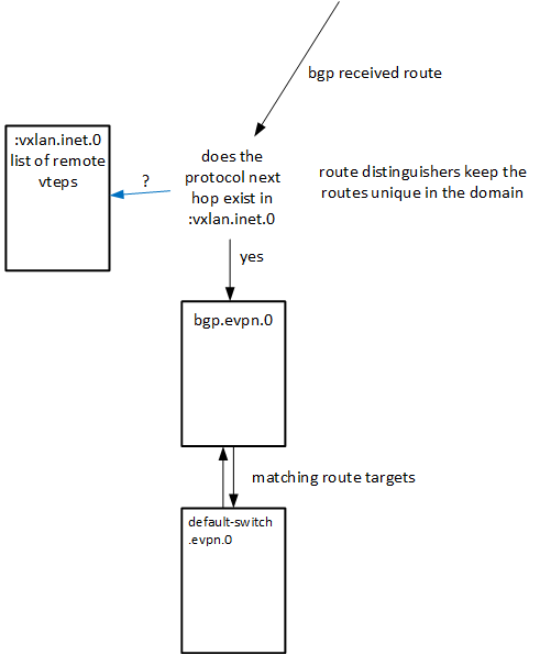
Quick word on Route Target VS Route Distinguishers,
These are similar but have distinctly different jobs, and yes initially its a bit confusing.
BGP was designed without MPLS and without the need to DISTINGUISH between different customers prefixes, its was just one big happy routing table, so BGP was expanded to accommodate this using what are called “sub address family’s” SAFIs. These are the extensions that allow BGP to DISTINGUISH between Customer A 192.168.0.0/24 and Customer B 192.168.0.0/24. the route DISTINGUSHER is added and routes can all be unique in BGP.
Now if you have multiple customers can you not just use the RD to put the routes into the respective customers tables ?, this is what I thought !, why do we need another marker, put simply that is not flexible enough.
A Route Target does a very similar Job but Targets are more flexible, with these you can pick a choose what VRFs your route will eventually be imported into. In a later lab we will setup a mutil VRF ( muliple customer seneraio ) and use different route targets for different customers.
Network Fun Times has a good explanation here.
Put simply Targets are more flexible, the example given to me was if your were a ISP you might to add some route like a management system into every customer this could be implemented simply enough by adding a policy to import route with community X in to each VRF
In my next lab I will expand on this by introducing the ability to dual home across muliple leaf devices. This is introduce some of the real power of a EVPN and VXLAN this is where I had my light blub moments of how really powerfull this technolgy will be and how it will resolve many of my real life problems.
Here are the full configs for this lab
https://github.com/simondbingham/evpn-and-vxlan-lab1
https://www.eve-ng.net/forum/viewtopic.php?f=13&t=19551